Jack B. Reid
jack@jackbreid.com
Github profile: jackreid Hosted on GitHub Pages — Theme by mattgraham
Development of a Single-Input Multiple-Output Optimization Method for Matching Shock Response Spectrums with a Set of Decaying Sines
Summer 2015
During the summer between my undergraduate at Texas A&M University and my graduate program at MIT, I worked at Sandia National Laboratories in the Solid Mechanics & Shock Physics Department. While I worked on several projects that summer, the primary one (and the only one approved for public release) focused on the development of an algorithm to generate a shake table procedure that would, as close as possible, generate target shock responses in multiple different parts of the test article. A poster version of this page is available here.
Shaker shocks are designed to match real-world shock intensity and are often applied at the point of interest on a component. However, it is sometimes infeasible to apply the shock at the point of interest and often there are multiple points of interest on the same component. Since the shaker can only apply a single input signal, while in application the component is exposed to multiple simultaneous excitation signals and different boundary conditions, the shaker cannot induce a precise desired shock response at each point of interest simultaneously. The purpose of this project is to create an optimization algorithm that can create a “best-fit” shaker input to induce desired shock response spectrums (SRSs) at an arbitrary number of points of interest with unique transfer functions based on a user-supplied weighting.

Background
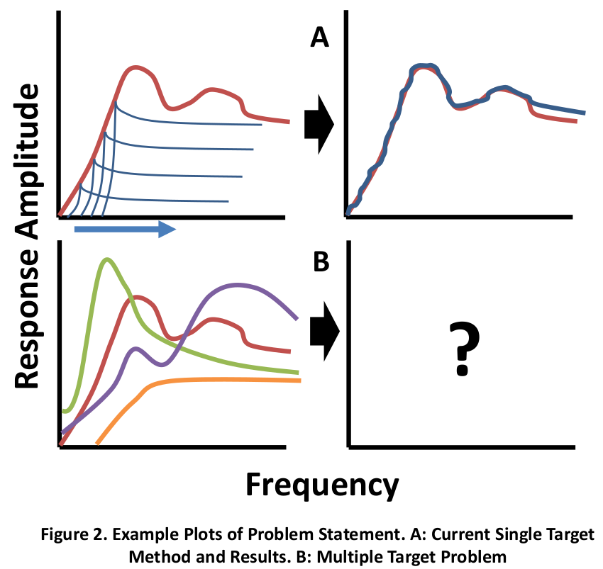
A former Sandian, David Smallwood, created an optimization algorithm for developing a shaker input that would result in a response of desired severity. This algorithm tries to match the desired shock spectrum one frequency at a time, moving from low frequency to high frequency, using a set of decaying sine tones (Figure 2A). This method relies upon the fact that low frequency sine tones have significant impact upon the shock responses of higher frequency sine tones, but the opposite is not true. As a result, each subsequent sine tone only slightly affects the lower frequency responses. Once a full sweep across the frequency range is completed, the process can be repeated one or more times to minimize the small discrepancies that do occur.
This method has several limitations, chiefly that can only optimize for a single target point of interest at a time, and assumes that the shaker and this point of interest are coincident, meaning that there is no transfer function between shaker behavior and target response. This project seeks to overcome these limitations and allow for multiple points of interest, with importance weighted by the user, and different transfer functions to each point of interest (Figure 1, Figure 2B).
Sum of Decaying Sines
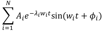
Where 𝐴 is the initial amplitude of the tone, 𝜆 is the decay rate, 𝑤 is the frequency in radians, and 𝜙 is the delay. This optimization algorithm requires the user to select the frequencies, decays, and the delays. The algorithm then optimizes the amplitudes, while maintaining the sign of each amplitude for shaker table stability purposes.
This equation and general concept holds for both the original algorithm and the new one developed in this project.
Error Definition
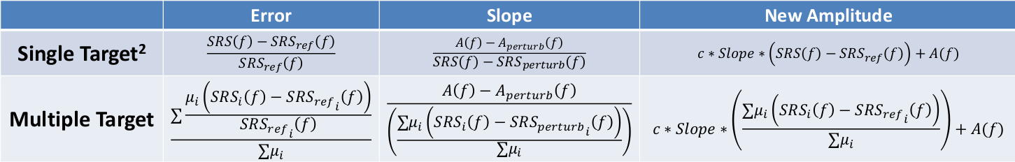
Error is based on a modified 1-norm with user supplied weighting vector. For example, a [1,1,1,1] weighting vector would mean four points of interest, each equally weighted. Meanwhile [2,1,1,1] would mean that the first point of interest is twice as important as any of the other individual points.
Optimization Algorithm
- Begin with “best-guess” set of decaying sine tones (can be calculated from reference SRSs)
- Use set of sine tones to generate acceleration time history and convolve with each transfer function to find acceleration time history at each point of interest
- Calculate SRS at each point of interest from acceleration time histories
- At lowest frequency of the sine tones, calculate the weighted error to determine direction of discrepancy (see above table)
- Perturb the sine tone at this frequency in the opposite direction of discrepancy
- Calculate resultant weighted Amplitude/SRS slope caused by perturbation (see above table)
- Use slope to move the specific sine tone amplitude in direction of discrepancy and thereby decrease the error (see above table)
- Recalculate error, if under tolerance, move to next frequency, else repeat this process
Validation Method
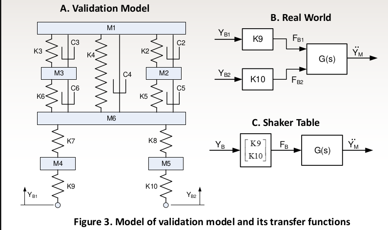
- Use a 8-DOF spring mass system (6 translation, 2 rotation) to as validation model. The center of masses of M1, M2, M3, and M4 are the points of interest (Figure 3A)
- Supply model with a displacement time history to both base inputs, plus a random noise signal to the second base (Figure 3B)
- Calculate SRSs at each point of interest to be used as target references
- Calculate transfer functions from each point of interest to a single input base (Figure 3C)
- Run optimization algorithm with a variety of error weightings and examine for validity
- Repeat for different types of noise, different input locations, and different target points of reference.
Results
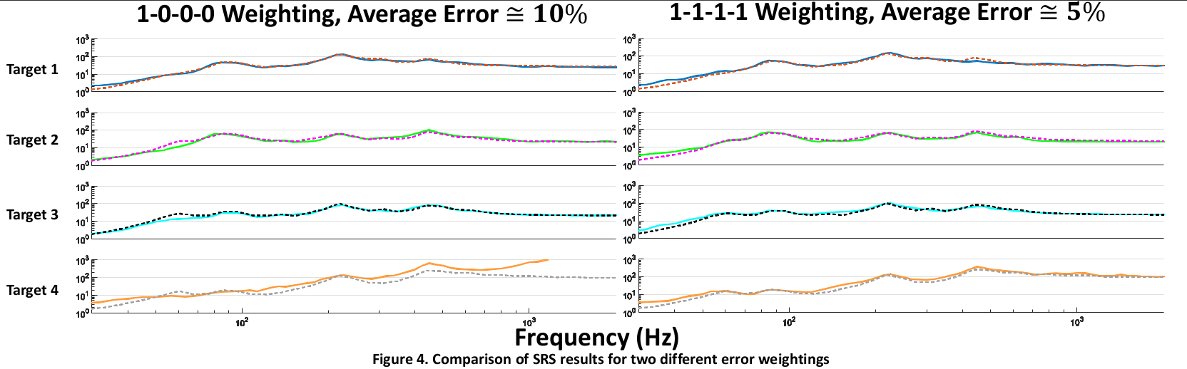
- Algorithm can overall successfully fit the multiple references
- It fails to reduce error to under tolerance of 5% at approximately 30% of frequencies, and under tolerance of 10% for approximately 15% of entries
- Error can be reduced more for even weightings [1 1 1 1] than for uneven weightings, such as [1-0-0-0]
- When weighting with zeroes in all but one entry, e.g. [1-0-0-0], and a uniform unity transfer function are input, this results in algorithm collapsing into Smallwood’s algorithm1 and achieves similar results (with small additional computational error)
- See Figure 4 for comparison of the results of two error weightings
Future Work
- Allow for user selection of norm-type for error, such as the ∞-norm which would result in the algorithm prioritizing the minimization of the largest error rather than the average error.
- Adjust optimization algorithm to prefer positive error to negative, for conservative results
- Further validation with experimental data is required
- Conduct an analytical examination of stability of algorithm and convergence time